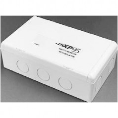
 Switch Monitor with Isolator, 55000-843IMCThe Context Plus XP95 Switch Monitor is designed to monitor the state of one or more single pole, volt-free contacts connected on a single pair of cables and to report the status to Context Plus compatible control equipment.FEATURES
The Switch Monitor provides four input states to the control equipment: âNormalâ, âFaultâ, âPre-alarmâ Â and âAlarmâ. The Switch Monitor has a red LED to indicate an alarm and two Yellow LEDs to indicate a switch input wiring fault or a loop short-circuit wiring fault.
The Switch Monitor is fitted with a bi-directional short-circuit isolator and will be unaffected by a single short-circuit on either loop input or output.
ELECTRICAL CONSIDERATIONS
The Switch Monitor is loop powered and operates at 17â28V DC with protocol voltage pulses of 5â9V. It is designed to accept a maximum line resistance of 50!. The end-offline Resistor required is 20k!.
MECHANICAL CONSTRUCTION
The Switch Monitor is supplied with a back box for surface mounting and is intended for indoor use only. Three LEDs, one red and two yellow, are visible through the front cover of the enclosure. The red LED can be illuminated under CIE control in the event of an alarm being detected.
One yellow LED is illuminated in the event of a fault condition being detected in the monitoring circuit and cannot be controlled by the CIE. The other LED is illuminated whenever the built-in isolator has  sensed a short-circuit loop fault.


